Cite this lesson as: Kim, J., & Deutsch, C.V. (2022). Calculation and Modeling of Variogram Anisotropy. In J. L. Deutsch (Ed.), Geostatistics Lessons. Retrieved from http://www.geostatisticslessons.com/lessons/variogramanisotropy
Calculation and Modeling of Variogram Anisotropy
Jinpyo Kim
University of Alberta
Clayton V. Deutsch
University of Alberta
July 5, 2022
Learning Objectives
- Determine the principal directions in anisotropic spatial data
- Understand variogram modeling in presence of anisotropy
- Appreciate issues in anisotropic variogram modeling
- Understand how to model variogram anisotropy in practice (source code available).
Introduction
A regionalized variable is anisotropic when the experimental variogram shows different behavior in different directions. Determining the principal directions of continuity is the first step in calculating reliable directional variograms from anisotropic data. Depending on the spatial data and geological understanding, there are several ways to find principal directions. This lesson reviews the challenge of determining variogram directions and anisotropy in the context of modern geostatistics; there are typically many variables across many domains, and tools to aid our geologic interpretation of expected anisotropy are useful.
The parametric form of variogram models is isotropic; anisotropy is accounted for in the distance calculation of each nested structure. The components of the distance vector are rotated to the principal directions, then scaled by range parameters (Wackernagel, 1998). The three rotation angles and three distance scaling parameters for each variogram structure must be established. The tolerance parameters for variogram calculation are chosen to balance stability and precision. Large tolerance settings will lead to less apparent anisotropy. Too small tolerance settings will lead to noise that masks variogram structure. These concerns and the general problem of calculating and modeling anisotropy in the variogram are reviewed in this Lesson.
Prerequisites
Understanding the geological conceptual model and visualizing the data are essential prerequisites. The spatial volume under consideration, orientation and limits of the drilling and domain boundaries are important factors to consider. In addition, the data must be considered in a reasonable coordinate system. Original real world UTM-Northing, UTM-Easting, and elevation (relative to sea level) are standard; however, in presence of faults, folds, and other deformations, a coordinate transformation may be required. This is not the subject of this Lesson, but must be considered.
The data must be cleaned and prepared for variograms. Compositing is often performed, normal score transformation may be required, outliers must be managed and errors in the data must be understood. Preliminary variogram calculation in the direction of drilling and omnidirectional variogram calculation in the plane of greatest continuity, or in all directions, provides a preliminary understanding of the continuity of the regionalized variable.
Determine the Principal Directions
Stratigraphic formations are continuous within a plane of continuity and show significantly less continuity perpendicular to this plane. Other depositional systems also show different continuity in different directions. The three principal directions are called the major, minor and tertiary directions. Sometimes they are called major, semi-major and minor. Three angles characterize the orientation of an ellipsoid of range values. Each direction is defined by two angles. Various methods can be used to determine the principal directions. Understanding the geological features and visualization of the geological data help the professional understand anisotropy. There are additional quantitative tools that are considered: variogram sphere, neutral model, variogram maps, and mass moment of inertia tensor (MOI).
Variogram sphere
The experimental variograms calculated in different directions show varying ranges and behavior in presence of anisotropy. Looking at many directional variograms simultaneously assists in detecting the directions of anisotropy. Directions are defined by two angles and could be considered as (1) vectors from the origin piercing the surface of the sphere, or (2) normal vectors on the surface of a sphere. The figure below shows the division of space and the experimental variograms in different directions. Those angles ensure that the perimeter of the circle with unit radius is divided equally. The vectors could be determined by a Fibonacci sphere where the points are approximately evenly distributed in three dimensions (RMSP). (Zagayevskiy & Deutsch, 2016) presents an alternative where vectors are distributed in 3-D for regular discretization.
. Example of a variogram sphere generated by the Resource Modeling Solutions Platform.](../images/variogramanisotropy/variogram_sphere.png)
Although the space is divided in a sphere, the range of the variogram shows anisotropy and the final model of the variogram ranges will appear ellipsoidal. It may be difficult to understand anisotropy by looking at all directions simultaneously, but automatic modeling of these directional variograms may provide insight (Resource Modeling Solution Ltd, 2020). The major, minor, and tertiary directions are inferred from the fit.
Neutral Model
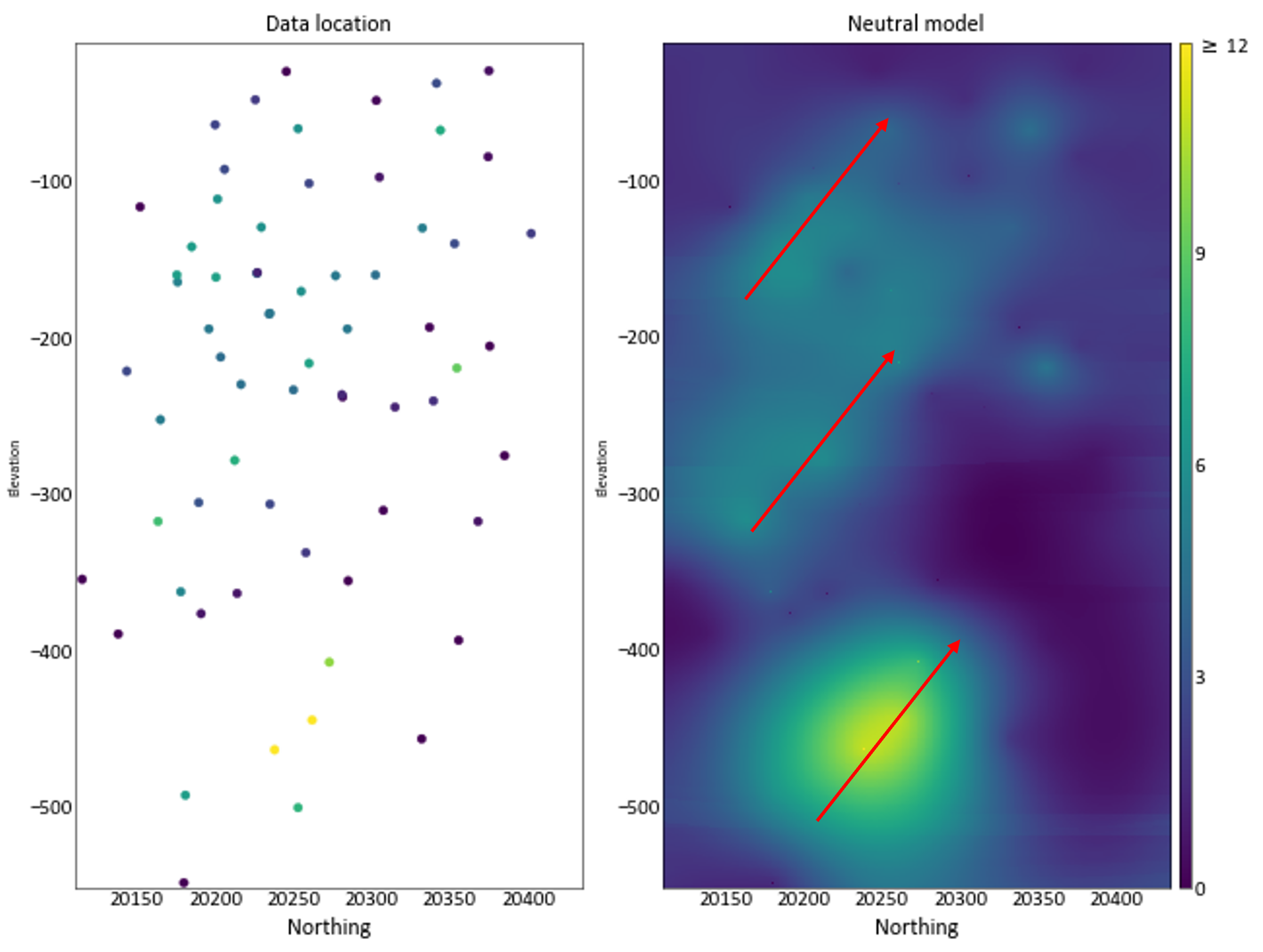
Visualizing drill hole data is influenced by the orientation and configuration of the drill holes. A block model that fills the entire geological volume is often easier to visualize and compute variograms for anisotropy determination. A neutral model is created by kriging or inverse distance without imposing any anisotropy except perhaps in tabular deposits where anisotropy perpendicular to the plane of continuity is considered. The figure shows a neutral model to assess directions of continuity. The neutral model could also be used to compute variogram maps to see the orientation, see next.

Variogram map
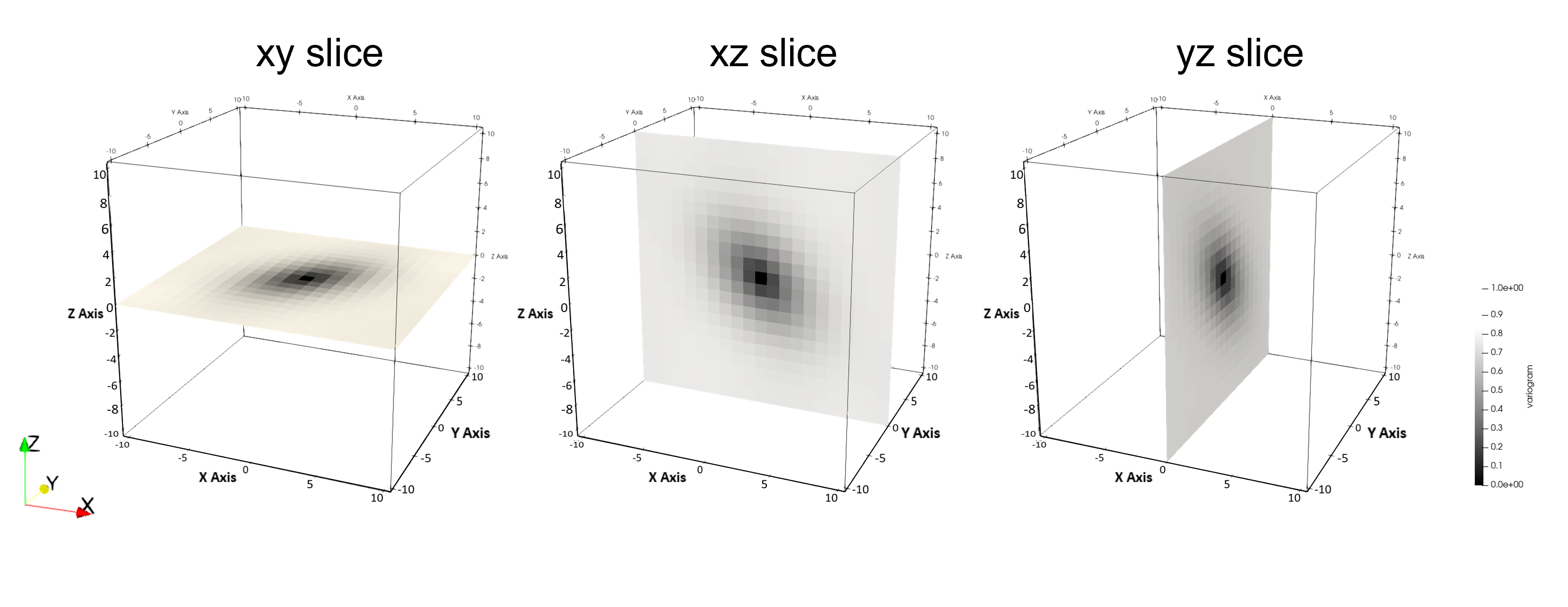
Variogram maps may reveal the principal directions through 2D maps of variogram values using polar coordinates. A higher spatial continuity along certain directions have a relatively greater autocorrelation along those directions (Samal, Sengupta, & Fifarek, 2011). This method computes variogram values for a grid of separation vectors creating a volume of variogram values. Variogram maps that include the origin are inspected to look for the principal directions. The figure shows how the volume could be sliced.

The three principal directions and estimates of the ranges could be obtained in the same way as the variogram sphere. It differs in that maps of variogram values are displayed instead of many directional variograms. Variogram maps may be easier to visualize and determine principal directions, but the directional variograms of the variogram sphere are often better suited for automatic fitting.
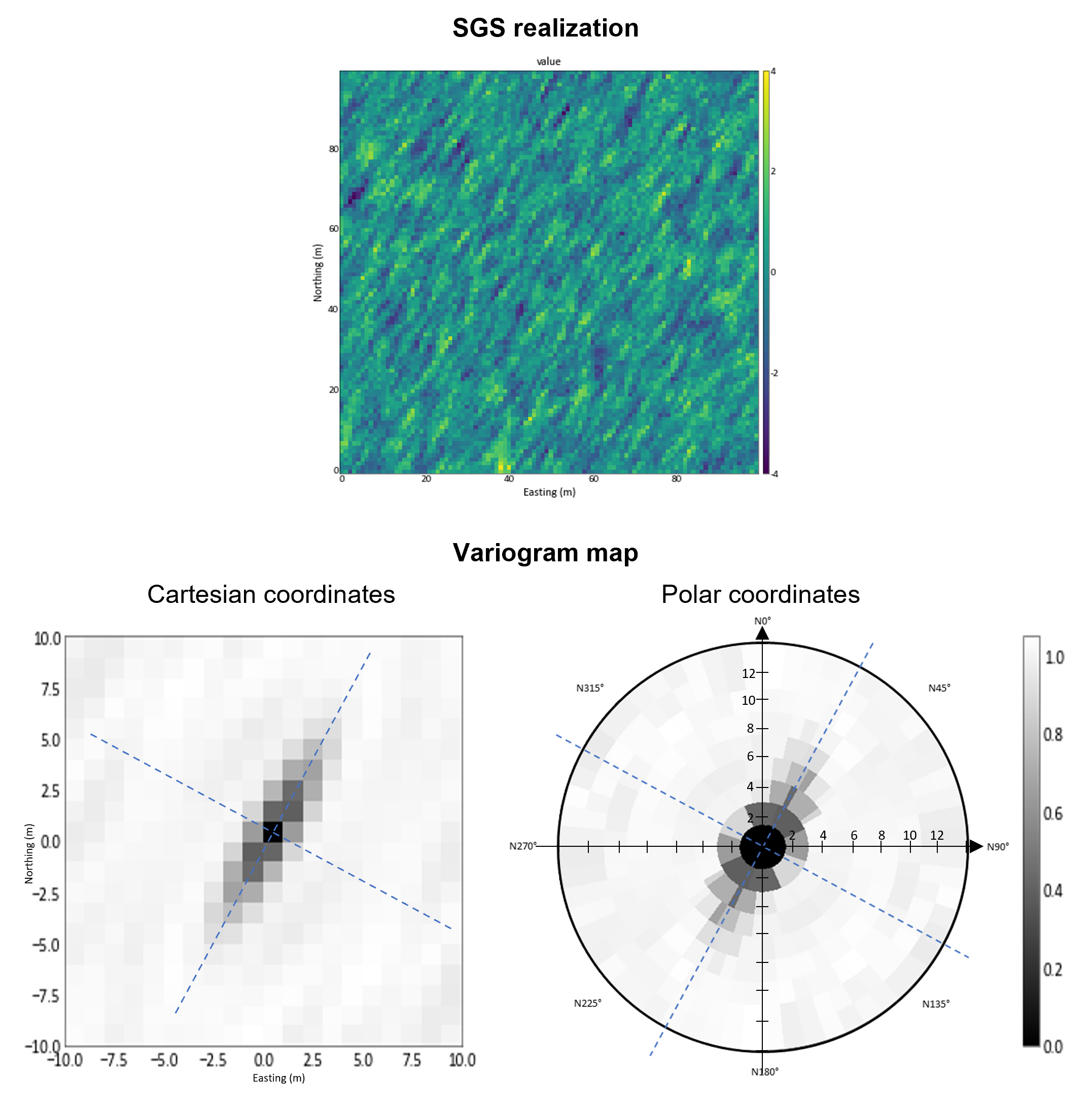
The figure shows an example of variogram maps in Cartesian and radial coordinates. The maps come from a Gaussian simulation with 4:1 anisotropy in the 30° direction. There are advantages and disadvantages to both presentations. If the underlying data are regularly gridded like a neutral model, then the Cartesian representation may be most suitable. If the data are scattered at irregular locations, then the radial coordinates may be more suitable.

Mass moment of inertia tensor (MOI)
The moment of inertia (MOI) tensor is the sum of the mass distribution occurring in a rigid body rotating about the axes of rotation. The principal direction of the MOI is the direction in which the rigid body is concentrated. The major direction is related to the smallest moment of inertia. This is shown following example. First, the covariance volume of the data is calculated as one minus the standardized variogram, then all values less than 0 are set to 0. In this case, the covariance volume was calculated from a Gaussian realization following GSLIB conventions of angle1=40°, angle2=-35°, and angle3=30°.
\[ w_{i}=\frac{1}{d_{i}^{2.5}} \]
\[ ( w \text{ is weight and } d \text{ is distance from } (0,0,0) \text{ where the value at position } i ) \]
The value of this corrected covariance volume has the meaning of mass, from which the MOI can be calculated.
\[ \mathrm{MOI}=\left[\begin{array}{ccc} 6813.566 & 1550.208 & -1491.566 \\ 1550.208 & 6068.564 & -2070.458 \\ -1491.567 & -2070.458 & 6168.618 \end{array}\right] \]
The principal directions are obtained from the eigenvectors by decomposition of the MOI tensor.
\[ \left[\begin{array}{ccc} I_{x x}-\lambda & I_{x y} & I_{x z} \\ I_{y x} & I_{y y}-\lambda & I_{y z} \\ I_{z x} & I_{z y} & I_{z z}-\lambda \end{array}\right] \cdot\left[\begin{array}{c} v_{x} \\ v_{y} \\ v_{z} \end{array}\right]=0 \]
\[ v^{\text{T}}=\left[\begin{array}{ccc} 0.590 & 0.569 & -0.573 \\ -0.807 & 0.379 & -0.453 \\ -0.041 & 0.730 & 0.683 \end{array}\right] \]
Since the moment of inertia is an anisotropic quantity and presented as a tensor, the principal directions can be determined by finding angles that would rotate the initial coordinate system such that the off-diagonal elements of the tensor are equal to 0 (Vasylchuk & Deutsch, 2017). The transpose eigenvector matrix is the rotation matrix \(R\). The principal directions and rotation angles can be computed from that matrix. The simplest approach is an exhaustive search over angle1, angle2 and angle3 with an objective to minimize the mismatch to the MOI-derived rotation matrix.
\[ R=\left[\begin{array}{cc} \cos (\beta)^{*} \cos (\alpha) & \cos (\beta)^{*} \sin (\alpha) \\ -\cos (\gamma)^{*} \sin (\alpha)+\sin (\gamma)^{*} \sin (\beta)^{*} \cos (\alpha) & \cos (\gamma)^{*} \cos (\alpha)+\sin (\gamma)^{*} \sin (\beta)^{*} \sin (\alpha) \\ \sin (\gamma)^{*} \sin (\alpha)+\cos (\gamma)^{*} \sin (\beta)^{*} \cos (\alpha) & -\sin (\gamma)^{*} \cos (\alpha)+\cos (\gamma)^{*} \sin (\beta)^{*} \sin (\alpha) \end{array}\right.\\ \left.\begin{array}{c}-\sin ( \beta ) \\ \sin (\gamma)^{*} \cos (\beta) \\ \cos (\gamma)^{*} \cos (\beta)\end{array}\right]\\ \]
\[ \begin{aligned} R=\left[\begin{array}{lll} R_{11} & R_{12} & R_{13} \\ R_{21} & R_{22} & R_{23} \\ R_{31} & R_{32} & R_{33} \end{array}\right] =v^{\text{T}} \end{aligned} \]
\[ \begin{gathered} \beta=\sin ^{-1}\left(R_{13}\right) \\ \alpha=\tan ^{-1}\left(\frac{R_{12} / \cos (\beta)}{R_{11} / \cos (\beta)}\right) \\ \gamma=\tan ^{-1}\left(\frac{-R_{23} / \cos (\beta)}{R_{33} / \cos (\beta)}\right) \end{gathered} \]
\[ \begin{gathered} \alpha_{1}=43.986, \beta_{1}=-34.965, \gamma_{1}=33.591 \\ \alpha_{2}=-136.014, \beta_{2}=241.965, \gamma_{2}=-146.409 \\ \\ (\alpha =\text { angle1, } \beta =\text { angle2, } \gamma=\text { angle3}) \end{gathered} \]
Experimental Variogram Calculation
Prerequisites to variogram calculation mentioned above include: (1) clean composite data assigned to the correct locations, (2) managed outliers, (3) appropriate data transformation, and (4) appropriate coordinate transformation. Experimental variograms are sensitive to the data configuration and experimental results should be assessed in the context of the underlying geological controls.
Tolerance Parameters
A detailed description of the definition and setting of the tolerance parameter can be found at the Lesson on tolerance parameters (J. L. Deutsch, 2015a). The lag spacing is chosen to coincide with the data spacing in each principal direction. The lag tolerance is usually chosen as half of the lag distance, but may be increased if there are few data and decreased if the data are regularly spaced. An angle tolerance of about 22.5° within the plane of continuity is standard. In tabular environments, the tolerance and bandwidth perpendicular to the plane of greatest continuity are carefully restricted (J. L. Deutsch, 2015b).
Apparent Anisotropy
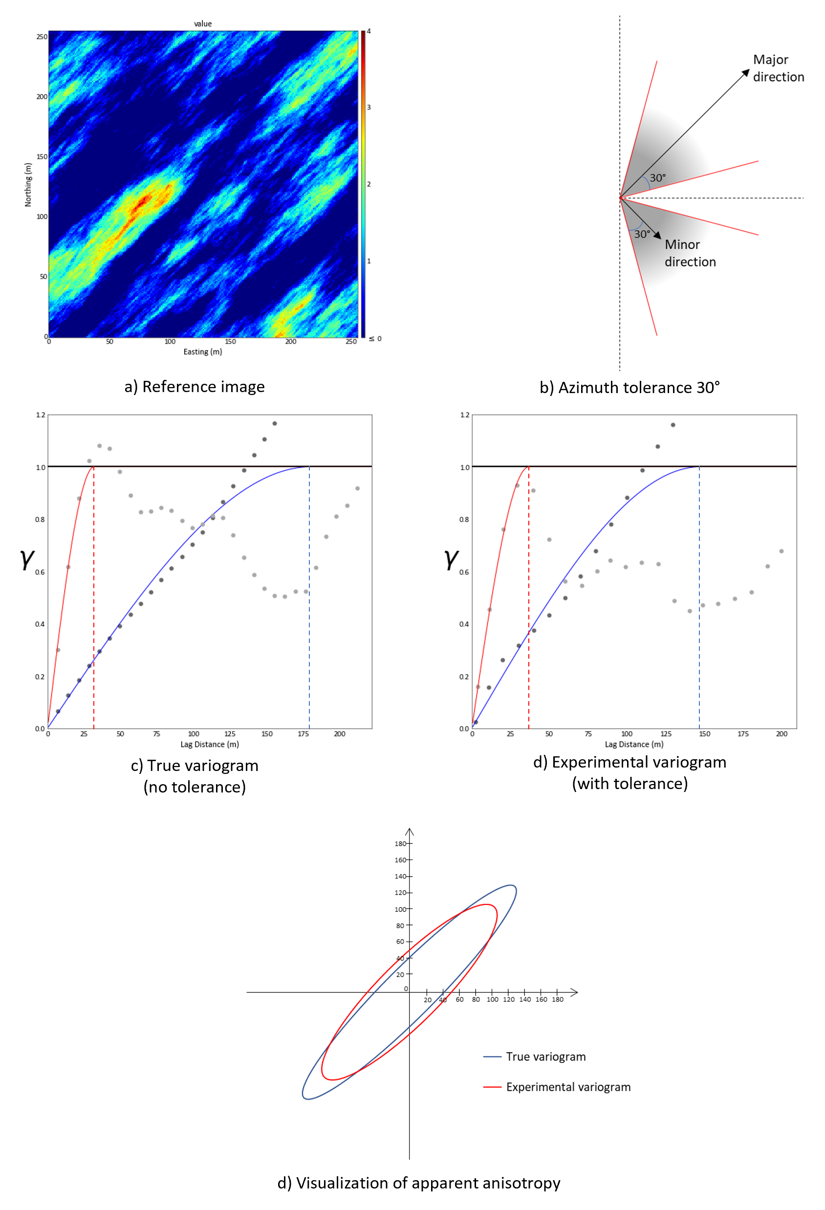
A large tolerance may be required to obtain stable variogram points, but this can lead to misleading spatial continuity. Large angular tolerance in presence of strong anisotropy will increase the apparent continuity in the minor direction and decrease the apparent continuity in the major direction (C. V. Deutsch & Journel, 1997). The smallest reasonable tolerance parameters should be used, permitting the increase of anisotropy ratios. The following figure shows an example of the error that occurs when the angular tolerances are set large.

Variogram modeling in anisotropy
The variogram model is inferred from the experimental variograms and expert judgement considering the conceptual geological model. The variogram model allows us to calculate the variogram value between any two points \((\textbf{u}_{1} [x_{1},y_{1},z_{1}] , \textbf{u}_{2} [x_{2},y_{2},z_{2}])\) within the stationary domain. The basic idea of modeling is the Linear Model of Regionalization (LMR) where the variogram model is a linear sum of variogram structures with different contributions (Hadavand & Deutsch, 2015).
\[ \gamma(\mathbf{h})=\sum_{i=0}^{n s t} C_{i} \Gamma_{i}(\mathbf{h}) \]
\(C_{i}\) are variance contribution to each nested structure, \(i=0\) relates to the nugget effect by convention, and \(\Gamma_{i}\) are licit variogram functions.
All variogram models are fundamentally isotropic. Anisotropy is accounted for in the distance calculation. Each nested structure could have a different orientation and range parameters for the principal directions if justified by geological interpretation. A lag vector is expressed as:
\[ \textbf{h}^{\text{T}}=(\textbf{u}_{1}-\textbf{u}_{2})^{\text{T}}=\left[x_{1}-x_{2}, y_{1}-y_{2}, z_{1}-z_{2}\right] \]
that is rotated to align with the principal directions of anisotropy:
\[ \left[\begin{array}{c} h_{\text {major}} \\ h_{\text {minor}} \\ h_{\text {tertiary}} \end{array}\right]=\left[\begin{array}{c} R \\ \end{array}\right]\left[\begin{array}{c} x_{1}-x_{2} \\ y_{1}-y_{2} \\ z_{1}-z_{2} \end{array}\right] \]
\(\left[\begin{array}{c}R \\\end{array}\right]\) is the rotation matrix. This matrix is calculated by three angles inferred and specified above. A detailed explanation of coordinate rotation can be found in Angle Specification (M. Deutsch, 2015).
The isotropic distance is obtained by dividing the vector components by the range in each principal direction.
\[ h=\sqrt{\left(\frac{h_{\text {major }}}{a_{\text {major }}}\right)^{2}+\left(\frac{h_{\text {minor }}}{a_{\text {minor }}}\right)^{2}+\left(\frac{h_{\text {tertiary }}}{a_{\text {tertiary }}}\right)^{2}} \]
The range parameters which depend on direction are fit during the variogram modeling process. The anisotropy is referred to as zonal when the range is beyond the domain size in that direction. The range parameter can be set arbitrarily large to model the variogram in this case.
Summary
Geological formations are almost always anisotropic. The first step in variogram determination is to establish the principal directions. Experimental directional variograms, variogram maps and MOI are useful tools to help with this first step. After finding the principal directions, it is necessary to compute reliable directional variograms. The tolerance and apparent anisotropy must be considered carefully. Variogram models consider all principal directions simultaneously with multiple structures as required.