Cite this lesson as: Deutsch, M. V. (2015). The Angle Specification for GSLIB Software. In J. L. Deutsch (Ed.), Geostatistics Lessons. Retrieved from http://geostatisticslessons.com/lessons/anglespecification
The Angle Specification for GSLIB Software
Matthew Deutsch
Maptek
October 13, 2015
Learning Objectives
- Describe the orientation of search ellipsoids and variograms using GSLIB angle conventions
- Understand the mathematical formalism of Euler angles in 3D space
- Transform between different rotation conventions
- Understand the practical application of angle specification/conversion (source code available).
Introduction
When performing geologic modeling it is necessary to orient anisotropy in three dimensional space. Experimental variograms are calculated in particular directions of interest, search ellipsoids for kriging and simulation are oriented along directions of geologic continuity, and even the underlying coordinate system may be re-oriented for modeling efficiency. Correctly orienting objects in 3D is a difficult task, due primarily to cryptic parameters and many different conventions. This lesson will explain how the most common kinds of parameters operate, and the mathematics behind them so that geologic modelers can efficiently and accurately specify orientations.
This lesson will use and explain the conventions behind the GSLIB (Deutsch & Journel, 1998). The underlying principles explained here will also allow for modelers to transform between different conventions.
Orientation in 2D
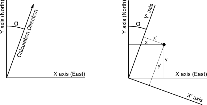
Orienting an object or coordinate system is substantially easier in 2D than in 3D. A single angle may be used to describe the rotation. In geologic modeling we generally consider the azimuth, or bearing, which is denoted \(\alpha\). This angle is measured positive clockwise from the Y axis (North). This is shown in the below figure.

When orienting a new coordinate system any point \((x, y)\) may be transformed into a rotated point \((x', y')\) using the following equations:
\[ x' = x \cdot \cos(\alpha) - y \cdot \sin(\alpha) \] \[ y' = x \cdot \sin(\alpha) + y \cdot \cos(\alpha) \]
which may be expressed in matrix notation as
\[ \left[ \begin{array}{c} x' \\ y' \end{array} \right] = \left[ \begin{array}{cc} \cos(\alpha) & -\sin(\alpha) \\ \sin(\alpha) & \cos(\alpha) \end{array} \right] \left[ \begin{array}{c} x \\ y \end{array} \right] \]
Euler Angles
Euler angles describe the orientation of an object or a coordinate system by describing a sequence of three elemental rotations. The rotations are called elemental because they occur about the axes of a coordinate system and not about some arbitrary vector. Any possible orientation can be achieved by performing three elemental rotations in sequence.
A 3D visualization of the Euler Angles used in GSLIB and CCG tools. Use the controls in the top right or drag the rings to orient the ellipsoid
There are two main categories of Euler angles; conventional Euler angles rotate about two different axes, and then the first axis again. For example you could rotate about the Z axis, then Y, and then the Z axis once more. However, more familiar to geologic modelers are the Tait-Bryan angles which rotate about each axis in sequence. For example the GSLIB angles rotate about the Z, X, and Y axes in order, and the conventional aircraft angles of yaw, pitch, and roll rotate about the Z, Y, and X axes. Tait-Bryan angles are still commonly referred to as Euler angles.
There are some important general considerations with Euler angles. There will always be two possible sequences of rotations to arrive at the same orientation. Consider a book on the desk in front of you with the spine pointing to the left and the cover pointing up. Define the X axis to be pointing to the right, the Y axis towards the screen in front of you and the Z axis pointing upwards. You could flip the book by rotating about the Y axis 180 degrees. Or, you could rotate first about the Z axis 180 degrees, then the X axis 180 degrees.
Also note that the sign of the rotation is important. Not only do different systems define the sequence of axes to rotate about differently, they may define the rotation direction differently. Generally azimuth is defined positive clockwise about the Z axis, but the remaining two rotations are not clear. Dip is sometimes measured positive downwards, but it may also be measured positive upwards as in GSLIB.
The Secret Handshake
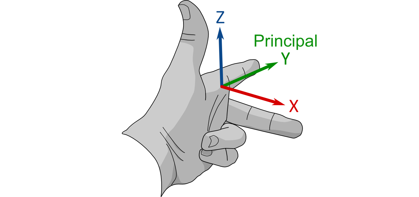
A common way that geologic modelers are taught about Euler angles is by means of a secret handshake. To begin, hold your left hand in front of you with your index finger pointing forwards away from you, your middle finger pointing to your right and your thumb pointing upwards. In this orientation your index finger is the principal direction (sometimes called major direction), the \(Y\) axis. Your middle finger is the minor direction, the \(X\) axis. Your thumb is the vertical direction, the \(Z\) axis. Provided that you are facing north, this orientation is described by the Euler angles \((0, 0, 0)\). This is shown in Figure 2.

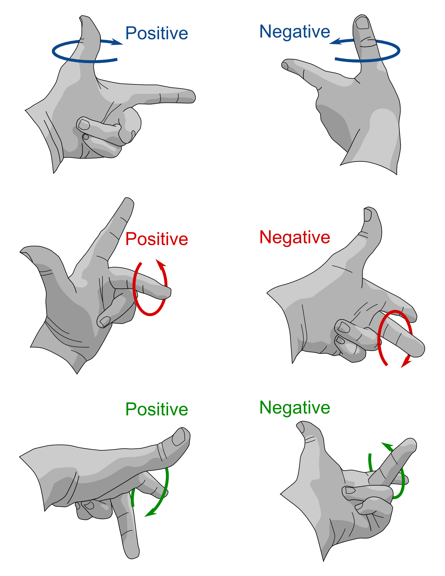
The first rotation is about your thumb (the \(Z\) axis). If you hold your thumb fixed, you are still able to rotate your index and middle fingers. If you rotate your index finger towards your middle finger this is a clockwise rotation and is a positive rotation. The second rotation is about your middle finger (the \(X\) axis), if you hold the middle finger fixed and rotate your thumb and index finger forward so that the index finger points downwards this is a negative rotation. The last rotation is about the index finger (the \(Y\) axis), if the index finger is held fixed and the thumb and middle fingers are rotated in a clockwise direction (looking away from the origin, along the index finger) this is a positive rotation. These sign conventions are described in Figure 3.

Rotation Matrices
Euler angles are most commonly used to create a rotation matrix, which then may be applied to achieve a new rotated coordinate system. A rotation matrix is a 3x3 matrix which may be used to transform any arbitrary vector \((x, y, z)\) to the new rotated coordinates \((x', y', z')\). It is often more computationally efficient to consider a rotation matrix over Euler angles.
The first rotation \(\alpha\) is about the \(Z\) axis, this is also called the azimuth. The \(Z\) axis remains unchanged while the \(X\) and \(Y\) axes are rotated in a clockwise angle \(\alpha\). Note the \(X\) and \(Y\) coordinates are expressed in the below equation as \(x_i\) and \(y_i\) as these are intermediate coordinates, and will be altered by the subsequent rotations.
\[ \left[ \begin{array}{c} x_i \\ y_i \\ z \end{array} \right] = \left[ \begin{array}{ccc} \cos(\alpha) & -\sin(\alpha) & 0 \\ \sin(\alpha) & \cos(\alpha) & 0 \\ 0 & 0 & 1 \end{array} \right] \left[ \begin{array}{c} x \\ y \\ z \end{array} \right] \]
The second rotation \(\beta\) is about the \(X_i\) axis, this is also called the dip. The \(X_i\) axis remains unchanged. This is measured negative downwards, and could be thought of as a counter clockwise rotation if you are looking at the origin from along the \(X_i\) axis.
\[ \left[ \begin{array}{c} x_i \\ y' \\ z_i \end{array} \right] = \left[ \begin{array}{ccc} 1 & 0 & 0 \\ 0 & \cos(\beta) & \sin(\beta) \\ 0 & -\sin(\beta) & \cos(\beta) \end{array} \right] \left[ \begin{array}{c} x_i \\ y_i \\ z \end{array} \right] \]
The third rotation \(\theta\) is about the \(Y'\) axis, this is also called the tilt. The \(Y'\) axis remains unchanged, as it is in its final orientation. This is a clockwise rotation if you are at the origin looking along the \(Y'\) axis.
\[ \left[ \begin{array}{c} x' \\ y' \\ z' \end{array} \right] = \left[ \begin{array}{ccc} \cos(\theta) & 0 & -\sin(\theta) \\ 0 & 1 & 0 \\ \sin(\theta) & 0 & \cos(\theta) \end{array} \right] \left[ \begin{array}{c} x_i \\ y' \\ z_i \end{array} \right] \]
These rotations can then be combined by matrix multiplication to get the following final matrix.
\[ R = \left[ \begin{array}{ccc} \cos\alpha\cos\theta + \sin\alpha\sin\beta\sin\theta & -\sin\alpha\cos\theta + \cos\alpha\sin\beta\sin\theta & -\cos\beta\sin\theta \\ \sin\alpha\cos\beta & \cos\alpha\cos\beta & \sin\beta \\ \cos\alpha\sin\theta - \sin\alpha\sin\beta\cos\theta & -\sin\alpha\sin\theta - \cos\alpha\sin\beta\cos\theta & \cos\beta\cos\theta \end{array} \right] \]
Rotation matrices are orthogonal by construction, and therefore \(R^{-1} = R^T\) which means that rotations may be reversed very easily by simply multiplying by the transpose.
Different Conventions
GSLIB considers the Y axis as the principal axis and the Euler angles rotate about the ZXY axes, with positive clockwise, positive upwards, and positive downwards. This is not the only convention out there. Given the three different axes to rotate about, and the dozens of possible sequences, along with the different sign conventions, and even different principal axes, it can be difficult to convert between formats accurately.
In some cases it may be simple to convert between conventions. For example, Vulcan considers the X axis to be the major axis, and the Euler angles rotate about the ZYX axes, with positive clockwise bearing, positive upwards plunge and a positive upwards dip. Vulcan also considers a 90 degree offset in the bearing as a consequence of labeling the X axis as the principal axis. Thus converting from GSLIB to Vulcan is a simple matter of inverting the sign of the last angle.
It may not be so simple. Before trying to derive the conversion see if either of the systems have a built in conversion tool, this should be able to convert the data correctly. However, It is always best to verify these tools as some have been known to have errors. To that end ensure that there is a way to check the conversion, some common ground is required. If the system has a method to visualize search ellipsoids (for example) then the orientations may be compared directly. However more elaborate methods may be required such as synthetic datasets or unconditional simulation with synthetic variogram models.
When converting, it may be necessary to find the common ground in a different representation. If you are able to construct the rotation matrix any set of Euler angles can be extracted (Slaubaugh, 1999). Or in some cases the quaternion representation of the orientation may be available, and again Euler angles may be extracted. This form of conversion is likely to be more robust than trying to convert the Euler angles directly, although degenerate cases must be explicitly handled.
Summary
GSLIB software use three angles to specify the orientation of search ellipsoids, variogram models, and for specifying directions when calculating experimental variograms. In this lesson these angles, as well as the underlying mathematics, have been explained. It is vital to understand precisely how these angles operate in order to use them and to convert between different representations.